By Linemen, For Linemen
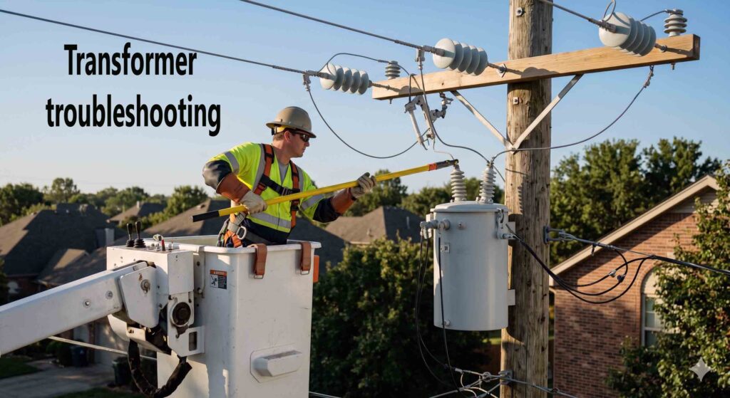
Hey brothers, when the storm clears or the dispatch hits at 2:00 AM for a localized outage, you aren’t just muscle with a pair of climbing gaffs and a hot stick—you are the field engineers of the grid. Distribution transformers are the literal workhorses of our infrastructure. When one fails, or behaves erratically, guessing isn’t an option. Making a mistake out there doesn’t just mean blowing a fuse link; it can mean a catastrophic arc flash or sending deadly back-feed down a line where your brother is working.
Today, we are diving deep into the technical grit of troubleshooting distribution transformers. We will break down the math behind transformer loading, look at the physical mechanics of internal faults, and establish a bulletproof diagnostic routine to keep you and your crew safe.
1. The Physics of the Fatal Trap: Back-Feed Dynamics
Before we crack open a tank or test an overhead canister, we must address the ultimate hidden killer in our trade: back-feed.
We all know the primary function of a step-down transformer. It takes your primary distribution voltage \(V_p\) and drops it to secondary utilization voltage \(V_s\) based on the turns ratio \(N\)
Where:
-
\(V_p\) = Primary Voltage (e.g., 7,200V)
-
\(V_s\) = Secondary Voltage (e.g., 240 V)
-
\(I_s\) = Secondary Current
-
\(I_p\) = Primary Current
If a 7200V/240V transformer has a turns ratio of exactly 30:1, It stepped down the voltage efficiently. But physics works both ways. If a residential customer fires up an improperly isolated standby generator or a commercial solar array malfunctions, it pumps 240V back into the secondary bushings.
Let’s look at the math of what happens on the open primary line:
That consumer-grade portable generator just energized your “dead” primary line to 7,200 Volts.
Brotherhood Safety Rule: Always isolate the secondary side entirely (pull the meter or drop the secondary leads) before treating the primary side as isolated, and never trust a line until you have tested it dead and applied personal protective grounds (PPG).
2. Calculating Real-World Transformer Loading & Thermal Stress
Overloading is the leading cause of premature insulation degradation. To diagnose whether a transformer has cooked itself, you need to calculate its thermal and electrical limits under load.
Let’s take a standard 50 kVA single-phase overhead transformer operating on a 7.2 kV primary system.
First, let’s calculate the rated full-load current on both the primary and secondary sides using the apparent power formula:
Where \(S\) is apparent power in Volt-Amperes \(VA\)
Primary Full-Load Current (\(I_p\) ):
Secondary Full-Load Current (\(I_s\) at \(240V\)):
If you hook up your clamp-on ammeter on the secondary leads during peak hours and read \(260A\), you are operating at:
Transformers can handle temporary overloading, but sustained operation above 100% causes the winding temperature to exceed its thermal design (typically a 65-degree-C to 10-degree-C rise limit). According to Arrhenius’ numbers for insulation life, every 8 degrees Celsius to 10 degrees Celsius increase above the maximum operating temperature cuts the mechanical life of the cellulose paper insulation in half.
3. The Technical Troubleshooting Protocol: Step-by-Step
When you approach a suspected failed transformer, structure your diagnostics logically. Do not rely on visual cues alone.
Step A: External Inspection and Pressure Relief
Look for blistering paint (high heat indicators), leaking dielectric fluid, or a bulged tank. Before doing anything else, pull the mechanical pressure relief valve using your hot stick. Internal faults can generate highly flammable gases (methane, ethane, hydrogen) under immense pressure.
Step B: Insulation Resistance Testing (Megger)
If the fuse link blew, do not simply slam in a new link and close the cutout. If there is an internal dead short, closing into it can cause a violent tank rupture. Use an insulation tester (Megger) to evaluate the integrity of the insulation system between windings and the tank ground.
Apply a 1000V or 2500V DC potential and measure the resistance:
-
Primary Winding to Ground (Tank): Should read high mega-ohms or giga-ohms.
-
Secondary Winding to Ground (Tank): Should read high mega-ohms.
-
Primary Winding to Secondary Winding: Tests for breakdown between the two coil systems.
Technical Benchmark: As a rule of thumb, a minimum acceptable reading is 1 Mega-ohm per KV of rating plus 1 Mega-ohm. For a 7.2kV winding, anything under 8.2 Mega-ohm indicates severely compromised insulation, contaminated oil, or moisture ingress.
Step C: Winding Continuity and Turns Ratio Test
Using a standard digital multimeter on the lowest (\(omega\) ) scale, check winding continuity.
-
A primary winding should show a consistent, low resistance reading (typically a few ohms to dozens of ohms, depending on the kVA size).
-
An open circuit reading (\(infty\) ) indicates a melted or snapped winding conductor inside the tank.
4. Root Cause Analysis of Core and Winding Failures
When a transformer suffers an internal failure, it generally falls into three categories:
-
Turn-to-Turn Short: This happens when the thin enamel or paper layer insulating adjacent copper/aluminum turns within a single winding breaks down. This creates a closed loop with zero resistance. Due to Ohm’s Law (\(I = V/R\)), massive currents circulate locally within that shorted turn, causing extreme pinpoint heating, oil boiling, and ultimate breakdown of the entire coil.
-
Phase-to-Ground Fault: A failure of the insulation barrier between the high-voltage winding layer and the grounded steel core or outer tank. This instantly draws massive fault current, tripping upstream protective devices (fuses or reclosers).
-
Ferroresonance: This is an unpredictable, non-linear electrical phenomenon that can occur on lightly loaded, three-phase systems supplied by long underground cables during single-phase switching. It causes extreme overvoltages (up to 300% of normal) that can saturate the core, generate loud whining noises, and violently burn out the transformer insulation within minutes.
Conclusion: Watch Each Other’s Backs
Out on the line, we don’t cut corners. If a transformer is acting up, take the time to run the diagnostic numbers, measure the currents, check the insulation, and isolate the secondary paths. Rely on your training, use your personal protective equipment, and remember that technical competence is just as critical as physical strength. Stay sharp, work the system safely, and ensure every brother goes home at the end of the shift.